
This post was written by Charles M. Fialkowski, director of product marketing for Siemens Process Automation.
In December 1993, the International Electrotechnical Commission (IEC) recognized five standard programming languages that could be used for implementing either process or discrete programmable controllers. The IEC is an organization that prepares and publishes international standards for all electrical, electronic, and related technologies, including controllers. The organization identified five programming languages and their common abbreviations as: ladder diagram (LD), instruction list (IL), function block diagram (FBD), structured text (ST), and sequential function chart (SFC). The third edition was published in February 2013.
The IEC developed these programming standards in response to the growing number of automation vendors, the growing complexity of applications, and the multiplying methods of implementing control functions. This article provides a brief overview of sequential function charts, describing proper implementation and common mistakes.
Overview
Sequential controls allow organizations to process sequential and parallel operations in a mode that is discrete with respect to time or events. They are used to coordinate different continuous functions, as well as to control complex process sequences. Depending on the defined state or events, operating and mode changes are generated, which results in a desired sequential implementation. Control system engineers learn to understand the interaction between the programs for basic automation and the sequential controls and how to generate sequential controls in their distributed control system.
Sequential controls specify one or several step sequences. The implementation of sequential control algorithms are generally referred to as sequential function charts. A step sequence is the alternating sequence of steps that trigger certain actions, respectively, and transitions that cause a step to change into another one when the corresponding step enabling condition is met. Each step sequence has exactly one start step and one end step and in addition may contain any number of intermediate steps that are interconnected through transitions. These transitions are triggered via “rising edge” signals. The diagrams may also generate feedback through loops within the step sequence. They can include parallel or alternative branches. In this case, however, the design must be done so that the sequence does not contain unsafe or unavailable segments.
To design sequential controls, a method called state diagrams may be used. State diagrams are easily learned, make automatic error diagnosis possible, and can be converted without a problem into many existing programming languages for sequence controls. However, designing parallel structures may not be possible, because a state diagram, by definition, is in exactly one state at any given time; otherwise, it cannot be considered a state diagram.
One of the core benefits of sequential controls is that all structures can be modeled and extensively analyzed, thus significantly reducing the time it would take to validate conventional structures. Sequential controls parameterize and activate lower-level logical control systems by setting corresponding global control signals. These control signals can have a brief or a lasting, a direct or a delayed effect. Sequential controls, as well as logical controls, have to support different operating modes. Particularly, manual control of the transitions and temporary or permanent interruptions of the process sequences have to be possible. In addition, process-specific protective functions are implemented with sequence controls.
Continuous and sequential controls
Within the scope of basic automation, different logic control systems are developed that implement a limited, clearly defined function. The functions continuously process input signals and generate corresponding output signals. By means of different control signals, the functions can also be activated and parameterized. To implement complex process sequences—for example, manufacturing recipes for products—it is necessary to coordinate the different functions and to activate them at the right time with the correct parameters. This task can be handled using sequential controls.
Sequential controls make step-by-step, event-discrete processing of sequential and parallel operations possible using step sequences. Depending on defined states or events, they generate operating and mode changes in the existing logic control systems and thus implement the desired sequential behavior.
Structure of step sequences
The step sequence is the alternating sequence of steps and transitions. The individual steps activate certain actions. The transitions control the change from one step to the next.
The first step of a step sequence is referred to as the start step. It is the unique entry point in the sequence and is always executed. The last step in a step sequence is referred to as the end step. It is the only step in a sequence that does not have a sequence transition. After the end step is processed, the step sequence is terminated, or processing starts again. The latter case is also referred to as a sequence loop.
Steps and transitions are connected to one another with oriented edges. It is possible to connect a step with several sequential transitions, as well as one transition to multiple steps. A transition is enabled if all series of connected steps are active and the step-enabling condition is met. In this case, first the immediately preceding steps are deactivated, and then the immediate subsequent steps are activated.
The simplest form of a step sequence is the unbranched sequence. Each step is followed by exactly one transition and the transition in turn by exactly one subsequent step. This implements a purely sequential run. Figure 1 shows the graphic basic elements, step (S) and transition (t).
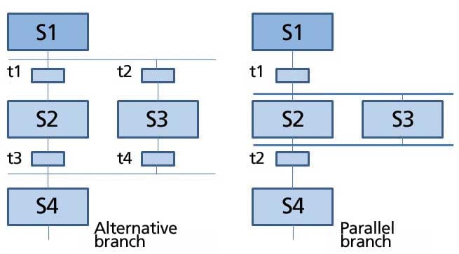 Figure 1. Basic Elements
Loops within the step sequence occur when by sequencing several steps, a cyclical run within a sequence is possible. The sequence loop represents a special case of a loop where all steps are run cyclically.
Another option for structuring step sequences is jumps. When a jump mark is reached, processing continues with the step where the jump mark points. Jumps within the step sequence can also result in loops. Because such a structure is difficult to follow, jumps should be carefully used and avoided altogether if possible.
Figure 2. Alternative and parallel branches
Figure 2 shows the structure of alternative branching with two branches. It is represented by bordering horizontal single lines with protruding ends. As can be seen, the alternative branches always start and end with transitions. After a step, several subsequent steps often must be processed simultaneously. In this case, the initial step has one transition that activates several subsequent steps at the same time. We call this structure parallel branching. The subsequent steps of the individual branches are processed independently of each other and are merged again. All branches end in a joint transition. Only after all branches are processed completely and the step-enabling condition for the subsequent transition is met is it possible to activate the joint subsequent step.
Figure 2 also shows the sequence of a parallel branch with two branches. They are represented with bordering horizontal double lines and protruding ends. As can be seen, the parallel branches always start and end with actions.
Building faulty step sequences by generating incorrect jumps and branches is a typical control engineering problem. Some of the most common faulty step cases are:
- Uncertain sequence: a step sequence that contains a structure whose availability is not ensured through the defined sequential performance
- Partially stuck: a step sequence with an internal loop that does not have the ability to become active. Although other steps within this loop are executed, the steps outside the loop are not. This makes parts of the step sequence unavailable.
- Totally stuck: a step sequence contains a structure for which no permissible step-enabling condition exists. In this case, the step sequence remains permanently in one state, and all other subsequent states are unavailable.
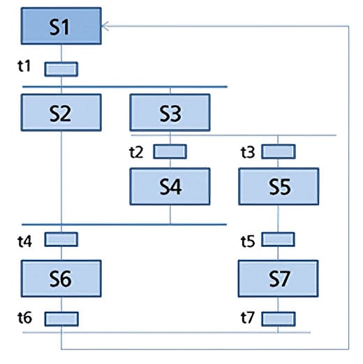 Figure 3. Uncertain structure
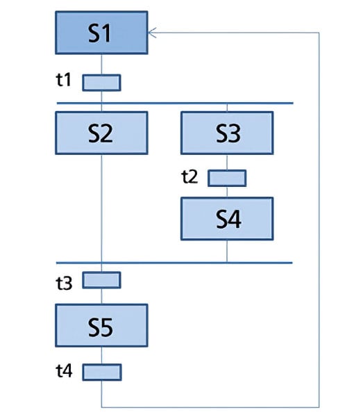 Figure 4. Illegal structure
Such structures are not permitted in step sequences and have to be eliminated with proper procedural design methods. Figures 3 and 4 show examples of two step sequences with impermissible structures. In figure 3, we cannot ensure that step S6 is available. In figure 3, we cannot ensure that step S6 is available since the alternative branch after step S3 goes active when transition t3 is enabled and execution passes to S5, and the parallel branch is merged again bypassing S6. This is an example of an uncertain structure. Figure 4 shows an example of an illegal structure, which will only execute once and then stops at step S4. Because step S2 is not active in this state, the parallel branch can no longer be merged in transition t3, which makes it totally stuck—making step S5 unavailable.
Reaction to faults in sequence controls
Particular operating modes have to be implemented to maintain adequate protection and conversion to manual if there is a fault.
- Automatic mode: The action of the step sequence is executed if the preceding transition is enabled.
- Manual mode: The operator triggers the action of the next step sequence, even if the preceding transition is not enabled.
- Mixed mode: The action of the step sequence is executed if the preceding transition is enabled, or if the operator triggered it. As an alternative, operator activation as well as enabling the preceding transition may be required.
The manual mode prevents the sequence control from being permanently blocked because of a fault. The mixed mode allows manual interruption of the sequence for testing or commissioning. The step-enabling conditions of all transitions of the sequence control have to be expanded accordingly.
Step sequences have to be able to react to faults in the controlled devices. Therefore, continuous fault monitoring is required. It recognizes and signals faults in the controlled devices. It makes automated safety of the plant possible by stopping the step sequence automatically if there is a fault. In addition, it has to be possible for the operator to stop and cancel the step sequence if there is a fault.
In both cases, corresponding protection functions have to be activated to take the plant to a safe state. If a sequence is stopped, it has to be ensured that it can be continued safely and in a way that is permissible regarding process engineering, even for a long interruption. In the sequence controls, process-specific protection functions are implemented, such as sequential locking of several devices if there is a fault in the process.
Sequence controls in a process control system
Many process control systems today implement controls with SFCs. They contain the step sequences and define their sequence topology, the conditions for the transitions, and the actions of the steps. It is possible to define priorities for the start conditions and the sequence characteristics separately for each step sequence. In addition, pre- and post-processing steps that are executed once before or after processing the step sequence can be defined.
Operating modes and switching modes
The performance of a sequence control in the process control system will depend on the following:
- The selected operating mode
- The specified switching mode
- The current operating mode
- The sequence options
Two different operating modes could be selected for sequence control:
- Auto: the program controls the sequence
- Manual: the operator controls the sequence through commands or by changing the sequence options
In manual mode, the following commands should be available to the operator to operate the sequence control:
Start, stop, halt, cancel, continue, restart, reset, and error
Depending on the selected operating mode, behavior of a step sequence can be controlled through different switching modes when further switching active steps to the subsequent steps.
- Switching mode T: The sequence control is running process control automatically. If a transition is enabled, the preceding steps are deactivated, and the subsequent steps are activated (T = transactions).
- Switching mode O: The sequence control is running operator control manually. The transition is enabled by an operator command. To this end, each subsequent transition of an active step automatically sets an operator prompt (O = operator).
- Switching mode T or O: The sequence control is running process controlled or operator controlled. The transition is enabled either through an operator command or a step-enabling condition that was met.
- Switching mode T and O: The sequence control is running process and operator controlled. The transition is enabled only based on an operator command and if the step enabling condition was met.
- Switching mode T/T and O: In this switching mode, we can specify whether the sequence is controlled by the process or the operator for each step individually. In the test mode, this allows us to define stop points in the sequence control (T/T = test transactions).
In the operating mode Auto, only the switching modes T, T/T, and O can be selected. The operating mode of the sequence control indicates the current state in the sequence and the resulting performance. Corresponding operating mode logic defines the possible modes, the permissible transitions between modes, and the transitional conditions for a mode change. Most process control systems define separate operating mode logic for sequence controls and for step sequences, respectively. It is possible to run step sequences depending on the mode of the sequence control.
Sequence options
By using sequence options, it is possible to control the execution time performance of sequence controls. For example, we can specify whether a sequence control is processed once or cyclically, or whether the actions of the active step are actually performed. In addition, time monitoring for the individual steps of a step sequence can be activated, which signals a step error if there is a timeout.
About the Author
Charles M. Fialkowski, CFSE, is director of product marketing for Siemens Process Automation in Spring House, Penn. He has more than 20 years of process automation experience in the chemical, petrochemical, and oil and gas industries, and has been involved in a number of process safety standards, including ISA84 and burner management with NFPA 85, 86, and 87. He is a graduate of Oklahoma State University with degrees in both electrical engineering and journalism.
Connect with Charles![]()
A version of this article also was published at InTech magazine.

