This post was written by Greg McMillan, industry consultant, author of numerous process control books, 2010 ISA Life Achievement Award recipient and retired Senior Fellow from Solutia Inc. (now Eastman Chemical).
Nearly every automation system supplier, consultant, control theory professor, and user has a favorite set of PID tuning rules. Many of these experts are convinced their set is the best. A handbook devoted to tuning has over 500 pages of rules. The enthusiasm and sheer number of rules is a testament to the importance of tuning and the wide variety of application dynamics, requirements, and complications. The good news is these methods converge for a common objective.
The addition of PID features, such as setpoint lead-lag, dynamic reset and output velocity limits, and intelligent suspension of integral action enable the use of disturbance rejection tuning to achieve other system requirements, such as maximizing setpoint response, coordinating loops, extending valve packing life, and minimizing upsets to operations and other control loops.
Potential performance
The purpose of a control loop is to reject undesired changes, ignore extraneous changes, and achieve desired changes, such as new setpoints. PID control provides the best possible rejection of unmeasured disturbances (regulatory control) when properly tuned. The addition of a simple deadtime block in the external reset path can enhance the PID regulatory control capability more than other controllers with intelligence built-in to process dynamics, such as model predictive control. In plants, unknown and extraneous changes are a reality, and the PID is the best tool if properly tuned. The test time has been significantly reduced for the most difficult loops. Simple equations have been developed to estimate tuning and resulting performance for a unified approach. (Equation derivations and a simple tuning method are in the online version.)
Control requirements
The foremost requirement of a PID is to prevent the activation of a safety instrumentation system or a relief device and the prevention of an environmental violation (RCRA pH), compressor surge, and shutdown from a process excursion. The peak error (maximum deviation from setpoint) is the most applicable metric. The most disruptive upset is an unmeasured step disturbance that would cause an open loop error (Eo) if the PID was in manual or did not exist. The fraction of open loop error seen in feedback control is more dependent upon the controller gain than the integral time since the proportional mode provides the initial reaction important for minimizing the peak error. Equation (1) shows if the product of the controller gain (Kc) and open loop gain (Ko) is much greater than one, the peak error (Ex) is significantly less than the open loop error. The open loop gain (Ko) is the product of the final element, process, and measurement gain and is the percent change in process variable divided by the percent change in controller output for a setpoint change. For most vessel and column temperature and pressure control loops, the process rate of change is much slower than the deadtime. Consequently, the controller gain can be set large enough where the denominator becomes simply the inverse of the product of the gains. Conversely, for loops dominated by deadtime, the denominator approaches one, and the peak error is essentially the open loop error. 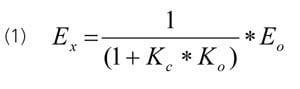 The peak error is critical for product quality in the final processing of melts, solids, or paste, such as extruders, sheet lines, and spin lines. Peak errors show up as rejected product due to color, consistency, optical clarity, thickness, size, shape, and in the case of food, palatability. Unfortunately, these systems are dominated by transportation delays. The peak errors and disruptions from upstream processes must be minimized. The most widely cited metric is an integrated absolute error (IAE), which is the area between process variable and the setpoint. For a non-oscillatory response, the IAE and the integrated error (IE) are the same. Since proportional and integral action are important for minimizing this error, Equation (2) shows the IE increases as the integral time (Ti) increases and the controller gain decreases.
 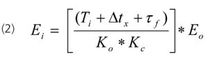 Equation (2) also shows how the IE increases with controller execution time (Δtx) and signal filter time (τf). The equivalent deadtime from these terms also decreases the minimum allowable integral time and maximum allowable controller gain, further degrading the maximum possible performance. In many cases, the original controller tuning is slower than allowed and remains unchanged, so the only deterioration observed is from these terms in the numerator of Equation (2). Studies on the effect of automation system dynamics and innovations can lead to conflicting results because of the lack of recognition of the effect of tuning on the starting case and comparative case performance. In other words, you can readily prove anything you want by how you tune the controller. IE is indicative of the quantity of product that is off-spec that can lead to a reduced yield and higher cost ratio of raw material or recycle processing to product. If the off-spec cannot be recycled or the feed rate cannot be increased, there is a loss in production rate. If the off-spec is not recoverable, there is a waste treatment cost. A controller tuned for maximum performance will have a closed loop response to an unmeasured disturbance that resembles two right triangles placed back to back. The base of each triangle is the total loop deadtime and the altitude is the peak error. If the integral time (reset time) is too slow, there is slower return to setpoint. If the controller gain is too small, the peak error is increased, and the right triangle is larger for the return to setpoint.
Process dynamics
The major types of process dynamics are differentiated by the final path of the open loop response to a change in manual controller output assuming no disturbances. (The online version shows the three major types of responses and the associated dynamic terms.) If the response lines out to a new steady state, the process is self-regulating with an open loop time constant (τo) that is the largest time constant in the loop. Flow and continuous operation temperature and concentration are self-regulating processes. If the response continues to ramp, the process is integrating. Level, column and vessel pressure, batch operation temperature, and concentration are integrating processes. If the response accelerates, reaching a point of no return, the process has positive feedback leading to a runaway. Batch or continuous temperature in highly exothermic reactors (e.g., polymerization) can become runaway processes. Prolonged open loop tests are not permitted, and setpoint changes are limited. Consequently, the acceleration is rarely intentionally observed. 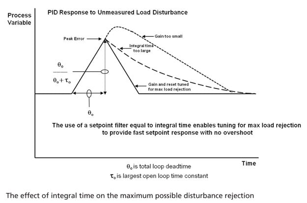
Unified approach
The three major types of responses have an initial period of no response that is the total loop deadtime (θo) followed by the ramp before the deceleration (inflection point) of a self-regulating response and the acceleration of the runaway response. The percent ramp rate divided by the change in percent controller output is the integrating process gain (Ki) with units of %/sec/%, which reduces to 1/sec. For at least 10 years, slow self-regulating processes with a long time to deceleration have shown to be effectively identified and tuned as "near integrating" or "pseudo integrating" processes, leading to a "short cut tuning method" where only the deadtime and initial ramp rate need to be recognized. The tuning test time for these "near integrating" processes can be reduced by over 90% by not waiting for a steady state. Recently, the method was extended to runaway processes and to deadtime dominant self-regulating processes by the use of a deadtime block to compute the ramp rate over a deadtime interval. Furthermore, other tuning rules were found to give the same equation for controller gain when the performance objective was maximum unmeasured disturbance rejection. For example, the use of a closed loop time constant (λ) equal to the total loop deadtime in Lambda tuning yields the same result as the Ziegler Nichols (ZN) ultimate oscillation and reaction curve methods if the ZN gain is cut in half for smoothness and robustness. Equation (3) shows the controller gain is half the inverse of the product of integrating process gain and deadtime. 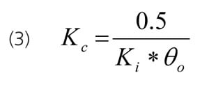 The profession realizes that too large of a controller gain will cause relatively rapid oscillations and can instigate instability (growing oscillations). Unrealized for integrating process is that too small of a controller gain can cause extremely slow oscillations that take longer to decay as the gain is decreased. Also unrealized for a runaway process is that a controller gain set less than the inverse of the open loop gain causes an increase in temperature to accelerate to a point of no return. There is a window of allowable controller gains. Also realized is too small of an integral time will cause overshoot and can lead to a reset cycle. Almost completely unrealized is that too slow of an integral time will result in a sustained overshoot of a setpoint that gets larger and more persistent as the integral time is increased for integrating processes. Hence a window of allowable integral times exists. Equation 4a provides the right size of integral time for integrating processes. If we substitute Equation 3 into Equation 4a, we end up with Equation 4b, which is a common expression for the integral time for maximum disturbance rejection. Equation 4a is extremely important because most integrating processes have a controller gain five to 10 times smaller than allowed. The coefficient in Equation 4b can be decreased for self-regulating processes as the deadtime becomes larger than the open loop time constant (τo) estimated by Equation 5.
 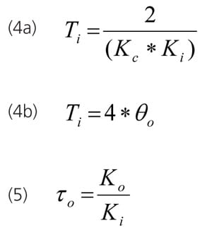 The tuning used for maximum load rejection can be used for an effective and smooth setpoint response if the setpoint change is passed through a lead-lag. The lag time is set equal to the integral time, and the lead time is set approximately equal to ¼ the lag time. For startup, grade transitions, and optimization of continuous processes and batch operations, setpoint response is important. Minimizing the time to reach a new setpoint (rise time) can in many cases maximize process efficiency and capacity. The rise time (Tr) for no output saturation, no setpoint feedforward, and no special logic is the inverse of the product of the integrating process gain and the controller gain plus the total loop deadtime. Equation 6 is independent of the setpoint change.
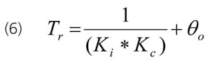
Complications, easy solutions
Fast changes in controller output can cause oscillations from a slow secondary loop or a slow final control element. The problem is insidious in that oscillations may only develop for large disturbances or large setpoint changes. The enabling of the dynamic reset limit option and the timely external reset feedback of the secondary loop or final control element process variable will prevent the primary PID controller output from changing faster than the secondary or final control element can respond, preventing oscillations. Aggressive controller tuning can also upset operations, disturb other loops, and cause continual crossing of the split range point. Velocity limits can be added to the analog output block, the dynamic reset limit option enabled, and the block process variable used as the external reset to provide directional move suppression to smooth out the response as necessary without retuning. The different closed loop response of loops can reduce the coordination, especially important for blending and simplification of the identification of models for advanced process control systems that manipulate these loops. Process nonlinearities may cause the response in one direction to be faster. Directional output velocity limits and the dynamic reset limit option can be used to equalize closed loop time constants without retuning. Final control element resolution limits (stick-slip) and deadband (backlash) can cause a limit cycle if one or two or more integrators, respectively, exist in the loop. The integrator can be in the process or in the secondary or primary PID controller via the integral mode. Increasing the integral time will make the cycle period slower but cannot eliminate the oscillation. However, a total suspension of integral action when there is no significant change in the process variable and when the process is close to the setpoint can stop the limit cycle. The output velocity limits can also be used to prevent oscillations in the controller output from measurement noise exceeding the deadband or resolution limit of a control valve preventing dither, which further reduces valve wear.
Bottom line
Controllers can be tuned for maximum disturbance rejection by a unified method for the major types of processes. PID options in today's DCS, such as setpoint lead-lag, directional output velocity limits, dynamic reset limit, and intelligent suspension of integral action, can eliminate oscillations without retuning. Less oscillations reduces process variability, enables better recognition of trends, offers easier identification of dynamics, and provides an increase in valve packing life.
Since the PID controller is a key part of almost every control loop and has significantly untapped capability, appendices are offered to help users get the most out of their PID controllers. The appendices also offer an insight and understanding that are useful beyond the tuning of controllers. The appendices are designed to help users see through the considerable complexity presented in the literature and get to the essence of process control opportunities feasting on the knowledge gained.
About the Author
Gregory K. McMillan, CAP, is a retired Senior Fellow from Solutia/Monsanto where he worked in engineering technology on process control improvement. Greg was also an affiliate professor for Washington University in Saint Louis. Greg is an ISA Fellow and received the ISA Kermit Fischer Environmental Award for pH control in 1991, the Control magazine Engineer of the Year award for the process industry in 1994, was inducted into the Control magazine Process Automation Hall of Fame in 2001, was honored by InTech magazine in 2003 as one of the most influential innovators in automation, and received the ISA Life Achievement Award in 2010. Greg is the author of numerous books on process control, including Advances in Reactor Measurement and Control and Essentials of Modern Measurements and Final Elements in the Process Industry. Greg has been the monthly "Control Talk" columnist for Control magazine since 2002. Presently, Greg is a part time modeling and control consultant in Technology for Process Simulation for Emerson Automation Solutions specializing in the use of the virtual plant for exploring new opportunities. He spends most of his time writing, teaching and leading the ISA Mentor Program he founded in 2011.
Connect with Greg:
![]()
A version of this article also was published at InTech magazine.