
This post was authored by Gary L. Pratt, PE, president of ControlSphere Enginering and Timothy L. Triplett, PE, founder, chief executive officer at Sacks Parente Golf and previously president of Coherent Technologies,
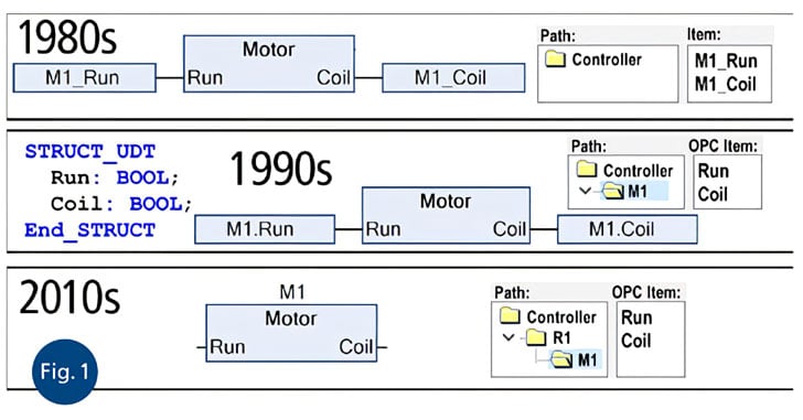
In the beginning…the world was flat. Or at least the industrial control system (ICS) programming namespace portion of the world was flat. In the 1970s when systems consisted of only a small number of tags, tag names could be simple (like T2). However, as systems grew in the 1980s, tag naming quickly became unwieldy. Engineers first began to add pseudohierarchy to names by embedding underscores (like M123_T2).
Then, in the 1990s, data structures (i.e., user-defined data structures [UDTs]) were introduced to the ICS programming world and became very popular over the next decade. With data structures, tags could now be structured, and multiple instances could be differentiated with the “dot” convention (M123.T2). However, this still required creating and instantiating structures and copying values into and out of these structures. In this decade, new standards allow direct access to function block hierarchical I/O, eliminating the need for UDTs, tags, and copying data.
Similarly, in the beginning, there was ladder logic. It was great for representing electrical equipment and simple discrete logic. However, as programming size and complexity increased, the choice of industrial control languages offered by controller vendors did not keep pace. As a result, ladder logic was recruited into purposes for which it was never intended and was poorly suited. Fortunately, the latest standards have programming languages and techniques that fill this gap and give 21st century industrial control system (ICS) programmers the tools they need to produce large, scalable, and maintainable programs—and allows ladder logic to return to the purpose for which it is best suited.
Just as UDTs transformed the 1990s, new features in OPC UA released in 2008 and IEC 61131-3 released in 2013 are transforming application programming in this decade. The new capabilities provided by these standards deliver unprecedented integration of control and the human-machine interface (HMI).
One of the most powerful features of IEC 61131-3 is its ability to nest function blocks (FBs) to any arbitrary width and depth using any of the IEC 61131-3 languages, and then to easily navigate the hierarchy by simply double clicking on any block to pop into its underlying code. This feature allows the ICS engineer to create a precise hierarchical representation of the plant and build each function within the plant in the best language for the task. For instance, engineers can use Continuous Function Chart (CFC) for high-level block diagrams, Sequential Function Chart (SFC) for state-based control, Ladder Diagram (LD) for discrete logic, and Structured Text (ST) for complex math, conditionals, looping, and bit manipulation.
The IEC 61131-3 CFC graphical language is a great tool for building a representation of the plant hierarchy. Typically, this begins with a single top-level block diagram of the plant called the plant view(PV), which instantiates additional subsystem PV block diagrams as necessary and ends with the control-and-equipment (C&E) view diagrams. The C&E view shows the complete control of a subsection of a plant with input equipment on the left, the control in the middle, and the output equipment on the right.
Within the C&E view, equipment models can be written in LD or ST, and typically deal with scaling, alarming, signal quality, latching, and manual override. The exact nature of the control block will depend on the type of control required. For instance, a process plant may use a CFC containing a startup sequence in SFC; proportional, integral, derivative (PID) from libraries; and other low-level control code written in ST. Control in a batch or discrete plant usually consists of an SFC describing the process sequence.
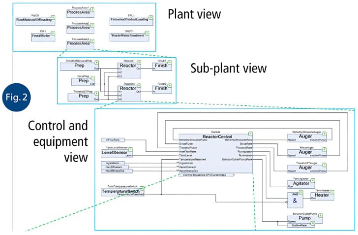
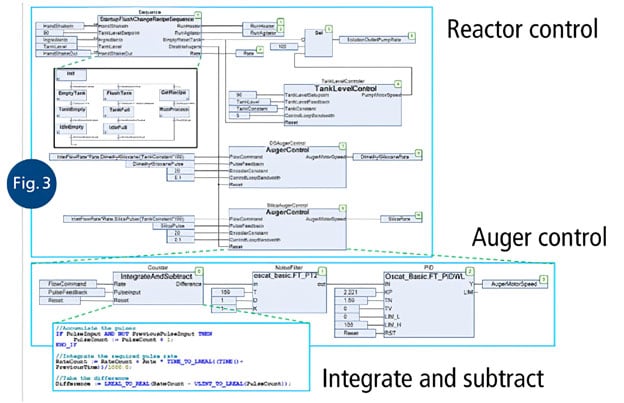
A typical multilevel hierarchical view is illustrated in figures 2 and 3. The plant consists of two levels of PVs, one level of C&E view, and several additional levels, each implemented in the language that is the best fit for the purpose. In this example, the PID and low-pass filters are from the OSCAT open-source industrial control library, and the block to integrate the incoming flow rate and compare it to the summation of the auger shaft-encoder pulses is implemented in ST. Imagine how simple this hierarchical multilanguage approach is for a plant technician to understand: drill down in the hierarchy to find the appropriate C&E view, examine the state of the control signals to determine if the problem is in the control or in the equipment, then push into that to diagnose the issue.
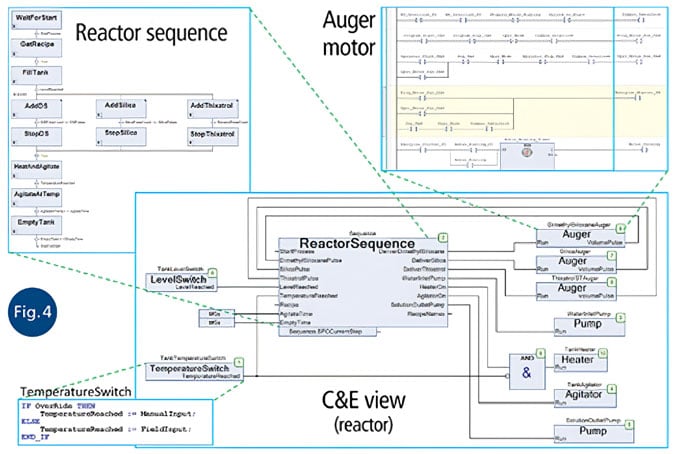
As alluded to earlier, a powerful benefit of the multiple languages of IEC 61131-3 is the ability to use the same tools for discrete, batch, and continuous process programming. In all types of programming, the plant-level views are similar, as are the input and output equipment in the C&E view. The only significant difference is the control block, which in a batch process is typically an SFC. Figure 4 shows a typical C&E view for a batch process with the control implemented in SFC, the temperature switch in ST, and the auger motor in traditional LD.
Obviously, an integrated control system is not complete without a seamless connection to its human-machine interface. Fortunately, the OPC UA standard makes this seamless connection possible with its platform independence, encryption, full hierarchical browsing, and meta-tags. Platform independence allows the OPC server to be placed directly in the industrial controller hardware (eliminating the expense and security vulnerability of an OPC server PC), and encryption ensures the security of the data and control. Hardware vendors can use true random number generators, crypto-coprocessors, and deeply embedded root of trust to further secure the connections to both the programming software and the HMI. Programming and HMI connections can be made through the open Internet while remaining protected from cyberattack or mischief.
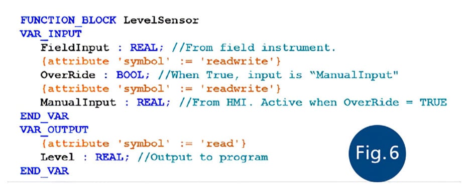
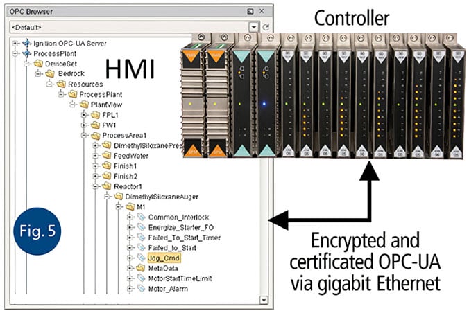 Figure 5 shows how OPC UA makes the entire hierarchy within the process plant available within an OPC UA tag browser (without explicitly connecting tags to objects or data structures within the ICS design or exporting tag lists). Within the control development environment, programmers can expose the entire namespace tree or select only certain branches. Tags can also be exposed directly in the code where their corresponding variable is declared (figure 6). The latter is especially handy for library parts with inputs and outputs that are intended to be used by the HMI.
Although figure 5 illustrates how all the necessary data is available throughout the design hierarchy, we would never want to deal with that complexity manually. Fortunately, with OPC UA, the HMI can browse the server and create matching complex tags with drag-and-drop simplicity. And if an HMI project is defined with a library of the same base objects as the control design, OPC UA provides enough information for the HMI to automatically create all the complex tags and their structures based on those.
To carry out this automation, the HMI begins by examining the tree from the top. Where it encounters objects in the OPC UA tree that have a corresponding item in the coordinated library, it instantiates that library object. Where it encounters objects that do not, it creates a new folder. It then continues down the tree, either finding and instantiating library objects, or creating further new folders until the complex tag is fully defined and instantiated. All the tags are automatically connected as this process proceeds. At the end, all that is left for the HMI is to organize the visual presentation.
In addition, meta-tags can be added to the control function blocks to provide additional information to the HMI system for it to automatically perform much of the visual presentation adjustment. For example, meta-tags can differentiate the type of process equipment associated with a complex tag structure, determining the default image presented by the HMI.
Figure 7 shows how the project hierarchy in the HMI system matches the project hierarchy in the control design. Figures 8 and 9 show the HMI screens corresponding to the continuous process control design in figures 2 and 3. Notice how the connectivity between the entire ICS and entire HMI designs is made with just the top-level tag name. Thousands of tags below may be automatically connected based on the hierarchy of the design.
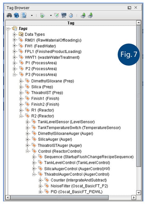
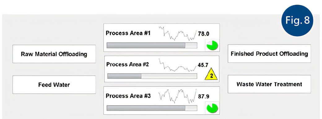
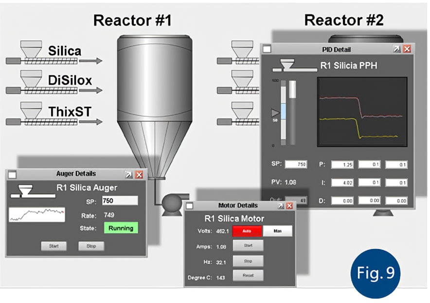
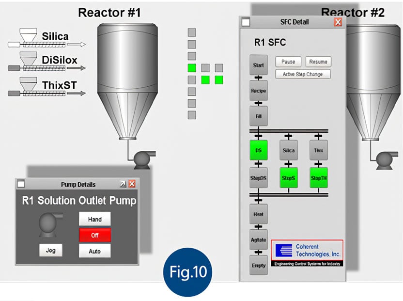
Figure 10 shows the corresponding screens for the batch control. Notice that the “ReactorSequence” block in the ICS library has a corresponding object in the HMI library that represents the current state of the process and allows the operator to manually override the process and select new active steps if an unusual situation occurs. Also notice that the HMI has pop-up screens for the motors in the process plant, and that these are all automatically created and connected based on the OPC UA hierarchy and associated library object templates.
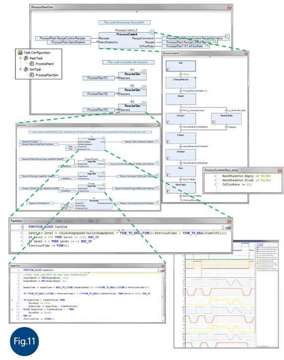
Figure 11 shows how the same IEC 61131-3 modeling can be used to create a complete plant simulation, which allows control system designs to be error-free the first time. With development systems that include a complete run-time PC with embedded OPC UA server, ICS engineers can create their control project and HMI screens, and completely test the entire system on a laptop. This results in the confidence that the design is complete and correct before commissioning begins.
The features of IEC 61131-3, OPC UA, and the latest ICS and HMI systems greatly streamline the process of creating ICS and HMI designs. The process is simply:
- Create an ICS design by instantiating items from the coordinated ICS/HMI library and user-created function blocks created from coordinated library objects.
- Connect the HMI system to the OPC UA server and read in the design hierarchy.
- Have the HMI system build a corresponding design using parts from the coordinated library and new subobjects.
- Organize the visual aspects of the HMI screens.
- Deploy the project.
The features in the IEC 61131-3 and OPC UA standards implemented in the latest ICS and HMI systems give automation system designers unprecedented integration capabilities. More than ever before, they can leverage best-in-class hardware and software to create larger, more scalable, more reliable, more maintainable, and more secure control systems. This stands as an example of how those who create and advance standards are paving the way for development of the tools that ICS programmers need for 21st century industrial control systems.
About the Author
Gary L. Pratt, PE, is president of ControlSphere Enginering. He previously was applications engineering manager for Bedrock Automation. Pratt has a broad background in technology that includes instrumentation and control, medical imaging, PCB, FPGA, IC, software design, and engineering and marketing management. He holds several patents in industrial controls.
Connect with Gary![]()
About the Author
Timothy L. Triplett, PE, founder, chief executive officer at Sacks Parente Golf. He previously was president of Coherent Technologies, Inc., an automation engineering company, and has more than 40 years of experience in distributed control system and programmable logic controller discrete, continuous, and batch control applications. He also holds several patents. A graduate of Texas A&M University, Triplett’s career has included being both an end user and a solution provider.
Connect with Hans![]()
A version of this article also was published at InTech magazine.

