This post was written by Greg McMillan, industry consultant, author of numerous process control books, 2010 ISA Life Achievement Award recipient and retired Senior Fellow from Solutia Inc. (now Eastman Chemical).
The reduction in inventories, coupled with changing market demands and fluctuations in raw material and energy prices, requires a process plant to respond as fast as possible for optimum operation. In order to change production rates or product grades, flows need to change in concert throughout the plant. Feedback loops can eventually find the right flows, but important time is lost and product quality may suffer in the interim. Feedforward control offers the ability to make the plant automation system respond immediately in unison.
Feedforward control can also compensate for composition, pressure, and temperature upsets before they have a significant impact on product quality. Feedforward can preemptively move a process to match the flows and conditions (e.g., temperature and composition) of all important process streams on a process flow diagram (PFD) for a given product and production rate, thereby enforcing material, component, charge, and energy balances for fed-batch and continuous processes. Plant-wide flow feedforward control provides the fastest possible and least disruptive transition to optimum operating conditions.
The setup
Feedforward has the ability to provide a preemptive correction of any disturbance that can be measured. The disturbance can be due to maintenance, abnormal conditions, operator actions, sequences, and changes in load (feed), raw materials, recycle streams, utilities, and environmental conditions. In feedforward control, a disturbance is measured, filtered, multiplied by a feedforward gain, passed through deadtime and lead-lag blocks for dynamic compensation, and used as the PID output with the proper direction (reverse or direct).
To get the maximum benefit from a feedforward signal, the correction must arrive at the same point in the process at the same time as the disturbance with an effect equal but opposite to the disturbance. For the timing and impact of the feedforward to be optimized, the gain, dynamic compensation, and action must be setup correctly. Often the feedforward benefits are stated in terms of the accuracy of the disturbance measurement. Statements that a 5% accurate feedforward measurement gives a 20:1 reduction in process variable error are impressive and are useful for getting the resources for feedforward. However, the user must realize feedforward performance also depends on feedforward noise and the accuracy of the feedforward gain and timing. The feedforward signal should be filtered so noise does not cause the PID output fluctuations to be larger than the control valve or variable frequency drive deadband inflicting disturbances on this loop and other loops. Fortunately, most feedforward signals become the setpoint for a flow loop whose gain is often in the range of 0.2 to 0.4.
The filtering of the disturbance needed to prevent noise from changing the final control element flow is correspondingly less because of the low controller gain. Sometimes flow feedforward signals are a setpoint rather than a PV to avoid the noise problem and to provide a more unison response. The feedforward gain must insure the magnitude of the feedforward signal is correct. The feedforward must provide a corrective change in PID output equivalent to the effect of the disturbance. If the feedforward signal is an input to the PID block with a feedforward scale, the scaling of the feedforward within the PID block takes care of the difference in engineering units between the feedforward signal and PID output. The feedforward gain depends on the magnitude of the change in PID output required for a change in the feedforward signal.
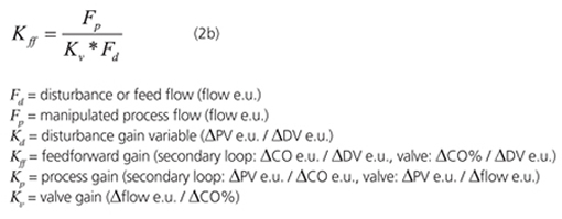
If the feedforward becomes the setpoint of a secondary loop (e.g., flow), the feedforward gain is the disturbance gain (Kd) divided by the process gain (Kp) for the primary loop using the engineering units (e.u.) for the process variable (PV) and the disturbance variable (DV) (Equation 1a). For flow feedforward, the feedforward gain is simply the ratio of the manipulated process flow to the disturbance or feed flow (Equation 1b). If the feedforward becomes the signal to a control valve instead of a setpoint to a secondary loop, the disturbance gain must be divided by the product of the valve gain (Kv) and the process gain (Equation 2a). For flow feedforward, the ratio of process flow to disturbance flow is also corrected by dividing by the valve gain (Equation 2b).
When the feedforward signal goes to a valve, the controller output (CO) is a % signal and the feedforward gain is inversely proportional to the slope of the installed valve characteristic that is the valve gain. This is an undesirable situation because the installed characteristic is nonlinear and varies with supply and destination pressures and the frictional losses in the system. Consequently, feedforward is predominantly used in the primary loop of a cascade control system whose output is the setpoint of a secondary flow loop. Equations 1a and 1b assume the PID output is in engineering units of the secondary loop. For a feedforward signal that becomes the setpoint of a secondary loop: 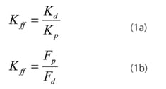 For a feedforward signal that is used to position a control valve:
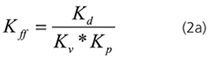
 Feedforward dynamic compensation must insure the timing of the feedforward signal is right. If the feedforward signal arrives too soon, the initial response of the PV will be in the opposite direction of the final response from the disturbance. The result is an inverse response. Feedback action tries to back out the feedforward correction, which results in a second peak in PV. If the disturbance arrives too late, a second disturbance is created from feedforward action. In both cases, an oscillation develops, and the error from the disturbance is increased.
To prevent a disturbance from arriving early, a deadtime is set in a deadtime block that is the deadtime in the disturbance path minus the deadtime in the correction path. Note that the paths must be to the same point in the process. If the disturbance arrives before the corrective signal due to excessive deadtime in the correction path, nothing can be done via dynamic compensation to make the feedforward arrive sooner. There is no function to undo deadtime. If the excessive corrective path deadtime is less than loop deadtime from the point of correction in the process to the PID input (sum of primary process and measurement deadtime), feedforward is still effective, but the feedforward gain should be reduced proportional to the ratio of the excessive corrective path deadtime to this loop deadtime. If the excessive feedforward deadtime is larger than this loop deadtime, feedforward will do more harm than good and should be omitted until changes in the final control element or secondary process can be made to decrease correction deadtime or increase disturbance path deadtime.
Often the disturbance originates from another loop such as level or an operator initiated change. A deadtime in the level controller output or operator initiated setpoint change can be inserted to delay the disturbance entry into the process. The disadvantage of the delayed action of a level loop or operator change may be less important than the advantage of a more accurately timed feedforward control. If the lag in the corrective path is smaller than the lag in the disturbance path, additional lag equivalent to the missing lag can be added to the feedforward dynamic compensation. If the lag in the corrective path is larger than the lag in the disturbance path, a lead time equivalent to the excessive lag can be added to the feedforward dynamic compensation.
While theoretically a feedforward multiplier would be used for a slope correction on a plot of the manipulated variable versus the disturbance variable, the choice of scaling factors is unforgiving with very little guidance to keep you out of trouble. Also the largest and most important feedforward measurement error is typically a bias. Even if a slope error existed, to see a significant disadvantage from a bias versus a span correction requires a wide range of operation. Additionally, a feedforward summer does not introduce nonlinearity. The nonlinearity of a feedforward multiplier might compensate for the change in process gain with flow for static mixers. However, for the more common case of composition, pH, or temperature control of vessels with some back mixing due to agitation, boiling, or recirculation, the change in process gain with flow is cancelled by the change in process time constant with flow in terms of the effect on the maximum controller gain setting making the multiplier nonlinearity undesirable.
Lastly, we live in a nonlinear world with complex process relationships and nonlinearities where a bias correction is the most foolproof solution. Flow feedforward is by far the most common signal because the process input manipulated by most process loops ends up being a flow. The disturbance is most often a feed flow. The process gain for temperature, composition, and pH is best quantified on a plot of the process variable versus the ratio of the manipulated flow to the feed flow.
The plots are based on an assumed composition and temperature of the feed. The plot of pH versus the ratio of manipulated reagent flow to feed flow, which is the titration curve from the lab, is based on an assumed concentration of acids and bases in the feed. The plot of column temperature versus ratio of manipulated distillate to feed flow is based on an assumed concentration of the components in the feed to be separated. More intelligent feedforward signals use measurements of concentration and temperature and first principle equations to provide a smarter ratio and hence feedforward gain.
A ratio station is used to provide the operator visibility of the desired and actual flow ratio and the ability to go to pure ratio control when the process measurement is out of service, out to lunch, or not representative of the process during startup. The feedforward control for a better operator interface is done external to the PID. The feedforward measurement is the input to a ratio block that has a ratio setpoint (desired ratio) and a PV (actual ratio). The output of the ratio block goes to a bias and gain block where the primary PID output is used to provide a feedback correction as a bias to the setpoint of the secondary flow loop being manipulated.
Opportunities
Coriolis flowmeters provide the best feedforward signals because these meters offer exceptional accuracy and rangeability, a true mass flow measurement for the mass balance, a temperature measurement, and an incredibly precise density measurement that could become an inferential composition measurement. Coriolis meters are capable of providing smarter and more accurate feedforward signals offering the opportunity for live process flow diagrams on the operator interface to show the true state of the process.
When energy costs are high, such as the cost of electricity and cooling water during the heat of the day, production rates can be ramped down quickly. At night production rates may be maximized when utility costs are low. For parallel trains of unit operations such as evaporators, heat exchangers, and crystallizers, feed can be proportioned to the more efficient units, which might be decided online by inferential measurements of overall heat transfer coefficients (UA). Some units may be shutdown to keep the feed rate to online units higher since the UA increases with flow.
For crystallizers, an inferential UA can be used to determine when a crystallizer should be defrosted and the flow divided among the remaining crystallizers. A similar strategy can be developed for catalyst or ionic bed regeneration. When units are started up, the units are brought to operating conditions based on ratio control before being switched to temperature or composition control. A change in feed to one unit operation has a widespread ripple effect to downstream unit operations. Flow feedforward can keep all the units in balance with the total production requirement without waiting on feedback controllers to see and correct an error from the unbalances.
Not only does an appreciable error have to develop for feedback correction, but the settling time (time for the process variable to stay close to setpoint) can be quite long, especially if there is any interaction between the loops. For day to night optimization, the production unit may be in constant state of disruption. If feed flows can be moved in concert quickly throughout the process, production rates can match changes in market demands without storing as much product. Reducing product inventory is important for reducing bottom-line costs.
Changes in product grade also require changes in existing feeds and the addition and deletion of feeds. The transition time and off-spec product can be minimized by the use of flow feedforward throughout the units. Model predictive control (MPC) is used to increase process efficiency by the manipulation of loop setpoints. A short and consistent rise time (time to reach a new setpoint), can make the MPC more effective. For batch operation and startup sequences, rise time may also be important. Setpoint feedforward can help provide a faster and more repeatable rise time.
To estimate rise time, Equation 3 can be used to see if setpoint feedforward (SPff) can appreciably reduce rise time (Tr). If the controller gain (Kc) is small or a structure is used with no proportional action on setpoint changes (Kc*DSP= 0), setpoint feedforward can be particularly effective. In Equation 3, the contribution from setpoint feedforward or from the proportional mode is limited to the maximum available change in the controller output (DCOmax), which is the difference between the PID output and the output limit. The integrating process gain (Ki) sets the maximum ramp rate of the PV. For convenience, the setpoint and controller output units are all in % of scale. 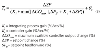
Special techniques
An unknown disturbance can be driving the process variable in the opposite direction of the measured disturbance. The use of feedforward control makes the upset worse because the feedforward correction is in the same direction as the unknown disturbance. The most common feedforward measurement is flow, and the least common is concentration. If there is a coincident decrease in feed concentration with an increase in feed flow, the strength of the feedforward control should be decreased.
For example, if the light key component concentration or waste acid concentration in the feed to a column or neutralizer, respectively decreased when the flow increased, the flow feedforward for temperature or pH control should be reduced, suspended, or even reversed. If the effect of the concentration change is greater than the effect of the feed change, the feedforward correction has the wrong sign. There are many unknown disturbances that may be driving the process variable (PV) away from setpoint when a measured disturbance occurs. The change in the process variable "delta PV" between a new and an old PV created by a deadtime block whose deadtime is set equal to the total loop deadtime can be used to make the feedforward smarter.
If the "delta PV" is divided by the process gain and a portion of this correction biases the feedforward signal with dynamic compensation, and the proper feedforward action applied (direct or reverse), the feedforward signal will be automatically adjusted to account for how much the PV is being driven by an unknown upset. The use of a deadtime block in the generation of the "delta PV" is a realization that feedback correction cannot occur sooner than one total loop deadtime. The correction for a positive rate of change only occurs when the controlled variable is above the setpoint plus some noise band. The correction for a negative rate of change only occurs when the controlled variable is below the setpoint minus some noise band. An unknown parameter in the charge, component, or energy balance or an unknown offset in the feedforward measurement can result in a bias error in the feedforward signal.
If a feedforward summer is used, the unknown shows up as a sustained feedback controller output correction. An integral only controller whose PV is the process PID feedback correction, whose scale is -100% to +100% correction, and whose setpoint is 0% correction can be used to adapt the feedforward signal. The output of the integral only controller slowly adjusts an input bias to the feedforward signal before being multiplied by the feedforward gain. The adaptation continues until the feedback correction of the feedforward by the process PID is nearly zero.
If batch units or continuous units that are going up and down are dumping into a surge tank, you have a tough scenario to achieve both maximum availability of the surge volume and maximum smoothing of the outlet flow by feedback control alone. Notch gain and error squared level controllers can help but are difficult to tune. Also, low controller gains cause slow oscillations from reset action unless the reset time is also increased so the product of the reset time and controller gain stays above a minimum. One solution is to add an adapted velocity limited feedforward.
For a surge tank level controller that manipulates the tank's discharge flow, the total of all flows dumping into the tank is a feedforward signal to set the discharge flow. If the flow engineering units are consistent, and there is cascade control of level to discharge flow, the feedforward gain is one. The question is what is the velocity or rate limiting needed to spread the disturbance from batch and on-off operations over the available surge volume. The time to violation of a level constraint is the difference between the current level and level constraint converted to a volume divided by half of the difference in volumetric flow into and out of the tank. The adapted velocity limit to take advantage of the available surge volume is simply the change in flow divided by the time to violation. 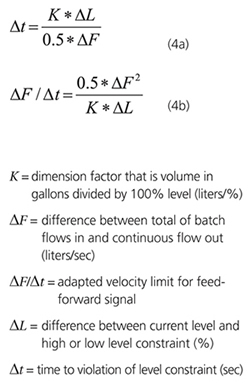 The only adjustment is to set a filter time for the batch flow that is equal to the normal amount of time the feedforward flow is zero. For a single batch operation upstream, this time would be the batch cycle time plus the average time between batches. For more information on this technique, see Appendix B - Batch to Continuous Transition in the book Advanced Control Unleashed: Plant Performance Management for Optimum Benefit, ISA.
Problematic applications
Excessive feedforward deadtime, insufficient feedforward sensitivity, shrink and swell, narrow timing windows, and missing secondary flow loops can eliminate the feedforward control advantage. If the disturbance is a vapor flow to an evaporator and the correction is a change in steam flow, feedforward does not do much better than a feedback PID tuned with a high gain because heat transfer lags delay the feedforward correction.
The use of pH feedforward for a feed pH on the flat part and a control point on the steep part of the titration curve will do more harm than good because the feedforward error from pH measurement error will be much larger than the control band. If shrink and swell can cause a drum level trip, feedforward control can aggravate the inverse response. In these cases, the temporary reversal of the feedforward action has been shown to help prevent trips. If the loop deadtime is small, the timing window for the feedforward signal is small. Also, a primary PID with the reset time proportional to the deadtime can provide fast feedback correction. Finally, for feedforward signals going to valves, the nonlinearity of the valve installed characteristic can cause overcorrection besides under correction.
About the Author
Gregory K. McMillan, CAP, is a retired Senior Fellow from Solutia/Monsanto where he worked in engineering technology on process control improvement. Greg was also an affiliate professor for Washington University in Saint Louis. Greg is an ISA Fellow and received the ISA Kermit Fischer Environmental Award for pH control in 1991, the Control magazine Engineer of the Year award for the process industry in 1994, was inducted into the Control magazine Process Automation Hall of Fame in 2001, was honored by InTech magazine in 2003 as one of the most influential innovators in automation, and received the ISA Life Achievement Award in 2010. Greg is the author of numerous books on process control, including Advances in Reactor Measurement and Control and Essentials of Modern Measurements and Final Elements in the Process Industry. Greg has been the monthly "Control Talk" columnist for Control magazine since 2002. Presently, Greg is a part time modeling and control consultant in Technology for Process Simulation for Emerson Automation Solutions specializing in the use of the virtual plant for exploring new opportunities. He spends most of his time writing, teaching and leading the ISA Mentor Program he founded in 2011.
Connect with Greg:
![]()
A version of this article also was published at InTech magazine.