
This post was authored by Ingemar Lidhamn and Marianne Lindeborg.
In the town of Örebro, 124 miles (200 km) to the west of Stockholm, Sweden, the tall chimney of E.ON’s heating and power station is visible from a distance. White grey water vapor often billows out of the chimney from the biggest boiler, which is fired by bio fuels and heats the water for the district heating network and provides steam for the electrical production.
District heating is a common method of heating for property in Scandinavia. Large boilers in the power station heat hot water, which is pumped around in a submerged pipe network to properties where heat exchangers transfer the heat to the buildings’ own waterborne heating systems. The properties are residential apartment buildings, office buildings, and detached houses, and in Örebro, there is also a historic castle, parts of which date back to the 1300s.
The heating and power station in Örebro has approximately 99% of all the buildings in Örebro connected to its district heating network; the network also extends to some smaller towns and in the Örebro county. Approximately half of the 280,000 inhabitants use district heating from E.ON for heating and hot water. In a normal year, the heating and power station with three boilers produces approximately 1 TWh (terawatt-hour) of heating. The boilers also provide steam to the turbines, which in turn are connected to generators that produce electricity, typically about 300 GWh (gigawatt-hour) per annum.
The largest and most efficient boiler, P5, is fired with bio fuels, such as sawdust, woodchips, bark, and turf, and has an output of 165–170 MW. It has a turbine and generator in common with the oil-fired boiler P4, and together the two have an output of approximately 300 MW heating and 100 MW electricity. In addition, the heating and power station has a hot water boiler of 140 MW, which is only used for peak loads during the coldest days of winter when the temperature can fall to below -22°F (-30°C). In addition to that, the district heating network gets a boost of 35 MW hot water from excess heat at a refuse facility 12 miles (20 km) from Örebro.
Environmental issues are always at the top of the agenda for E.ON’s heating and power station in Örebro. Three old boilers from the 1960s have recently been dismantled, and a new bio fuel fired boiler, P6, is being built in their place, which will reduce the heating and power station’s environmental impact still further. The new 70 MW boiler is fired with bio fuel, even twigs and stumps, and with that in operation, in a couple of years, the heating and power station’s environmental impact will be significantly reduced. In terms of environmental objectives, among other things E.ON is working with a concept called “Sustainable City,” where focus is on energy, waste, and transport. Together with Örebro, E.ON is planning the city’s sustainable development from a social, economic, and environmental perspective. The city has set high environmental targets, with a reduction of carbon dioxide by 40% per inhabitant for 2020.
Cogeneration technology is not the latest industry buzzword, since it is a proven technology that has been around for more than 100 years. Before there was an extensive network of power lines, many industries had cogeneration plants. In the U.S., the nation's first commercial power plant was a cogeneration plant that was designed and built by Thomas Edison in 1882 in New York. Primary fuels commonly used in cogeneration include natural gas, oil, diesel fuel, propane, coal, wood, wood-waste, and bio-mass. Cogeneration is also known as combined heat and power, or CHP. Cogeneration plants recover the "waste heat" that is otherwise discarded from conventional power generation to produce thermal energy. This energy is used to provide cooling or heating for industrial facilities, district heating systems, and commercial buildings. Through "waste heat recovery," cogeneration power plants achieve high efficiencies. A typical cogeneration system consists of an engine, steam turbine, or combustion turbine that drives an electrical generator. A waste heat exchanger recovers waste heat to produce hot water or steam. Cogeneration produces a given amount of electric power and process heat using less fuel than it takes to produce the electricity and process heat separately. The heat produced by cogeneration can be delivered through various mediums, including warm water (e.g., for space heating and hot water systems), steam, or hot air (e.g., for commercial and industrial uses). A simplistic example of a cogeneration process is an automobile where engine heat is used to warm passengers.
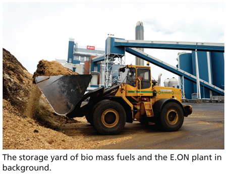
The fuel mix of the boilers consists to 20–30% of peat, and the rest is wood chips of various kinds. Samples are taken from the incoming fuels for analysis. Since the fuel is stored outdoor and analysis takes a day to process, the mixing of the various fractions of the fuels are done “by experience” of the driver in a front loader. He determines the quality and moisture content of the fuel and makes a good mix for the boiler that way.
“The new boiler makes a major contribution by replacing the old oil fired boiler. It reduces the CO2 emissions by 84,000 tons per annum, the equivalent of the emissions of 28,000 petrol powered cars. In addition, the transport of the bio fuel will be by rail instead of trucks to a much greater degree. It is part of our collaboration in Örebro city’s environmental objective of being a sustainable city,” said E.ON’s Jonas Vilhelmsson. E.ON Örebro has approximately 120 employees. It is owned by E.ON Värme Sverige AB, which delivers district heating in 45 networks and operates around 600 boilers in Sweden. E.ON Värme Sverige AB is part of E.ON Nordic, which produces and supplies energy in the form of electricity, gas, heating, cooling, and refuse treatment and energy-related services to the Nordic market. E.ON Nordic is part of the German E.ON group with over 90,000 employees and establishments in Europe, the U.S., and Russia.
Facts about Örebro
Örebro municipality with approximately 134,000 inhabitants runs several programs for "Sustainable City." A long-term environmental objective is to be a fossil-fuel-free city by the year 2050. By 2020, emissions of greenhouse gases must have been reduced by 40% compared to 2000. The program includes efforts to double the number of people traveling on public transport by train and bus by 2020. This is just one approach in the drive to reduce car traffic by 25% by 2020 in Örebro city, compared to the levels in 2000. There is also a major focus on reduced energy consumption in the municipality's 600 buildings, purchase of climate aware food for the city's food outlets, sustainable ecological wildlife care in the region, and investment in a toxin free environment and sustainable waste management.
The latter includes composting of all food waste and production of biogas for the city's buses. The climate load of Örebro has fallen in recent times. Between 2000 and 2009, the reduction was 11% across the whole county, calculated per inhabitant. At present, the climate load for an Örebro-er is equivalent to just over 11 tons of carbon dioxide per year. This figure needs to fall to below a ton by 2050. The declaration of objectives states Örebro municipality must be in the front line among Swedish municipalities and show that conscious climate work can contribute to increased quality of life and long-term sustainable economic development.
Control room
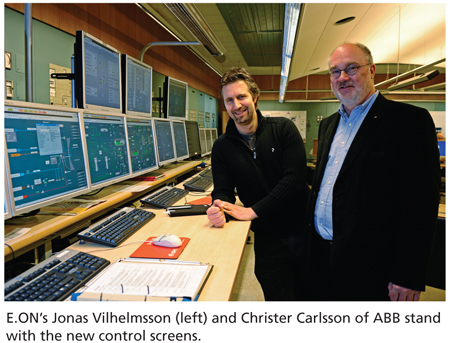
All processes in the heating and power station are controlled from a large and centrally located control room. Along the walls there are pulpits with sections of the heating and power station's older relay controls with knobs, pushbuttons, and dials, to some extent as reserve. But the present day control occurs at a few curved workstations with computer screens in front of comfortable chairs. Vilhelmsson, systems manager at the heating and power station, explains the three boilers, the turbine system for electrical production, and the water system where process water and smoke gases are cleaned and are all controlled from here.
"We aim to have the same operator system, ABB's automation system 800xA for Power Generation, for all the five process systems. The same systems give a better overview, simpler information handling, and easier maintenance-it is the best solution, both for the operators and for us system managers," he said. During the nearly 35 years that the heating and power station has been in operation, the automation systems for the processes have been successively modernized. The bio fuel fired boiler P5 was built in 1989, and around 2006, after 17 years of operation, it was definitely time for an improvement of the operator environment. "The boiler was controlled by an old command and control system Contronic E, supplied by Hartmann & Braun, which is today part of ABB, and the operator system CE-K was character-based. It was not good as a working environment; it started to become difficult to get replacement parts, and as mentioned, we wanted to have the same screen displays for all systems," he said.
Upgrade decision
E.ON decided to modernize and upgrade the system instead of replace it completely. This means the existing control system with cabinets, hardware, and configuration of signal management-the complete installation close to the processes-was retained unchanged, while the older screens and hardware for the two operator stations were replaced with a new and modern Windows-based system. The project was implemented during a few months summer shutdown in 2006. The operator stations were changed using new software and hardware connected to the existing control system, enabling migration and upgrade in stages, as service life extension of the system.
A new unit with three redundant system servers built a bridge between the existing process system and the new operator system. Fiber-optic cables were installed to provide communication between the old and new systems, for information exchange between the heating and power station operation information system and for communication to and from the control room. "Upgrading was the best alternative", said Vilhelmsson. "A complete replacement of the automation system would have been a large and extremely costly project that would have required recommissioning of the boiler. That was not feasible. An upgrade like this is a good intermediate stage, which means that we can run for several years before we need to take the next step." The whole project ran smoothly. "It went very well. ABB planned and converted the system, and when it was delivered, we only had to connect the communication buses together and run it. With a little fine tuning, it ran immediately, and the operators are very pleased," he said. "The display image is easy to manage, and the operators have adapted the images and the alarm systems to what they feel comfortable with."
In the control room, the displays for the P5 boiler show the whole process for the duty operators. The glowing bed of sand in the bottom of the boiler maintains an optimal 1544°F (840°C). At present, the boiler is fed with 82 tons of bio fuel per hour, and it produces hot water with an output of 138 MW. Steam at 986°F (530°C) is led to the turbine under high pressure, and the generator provides 41 MW of electricity. The process plays out across two workstations: one with three screens and one with two screens. Everything is easy to see with graphics, clear symbols, and easy-to-read lists of present and completed alarms.
Stations for each block
At the second workstation in the control room, three of the other processes are displayed with the same operator interface.
"We run each block individually, instead of a single flat system. This makes it possible to carry on even if one system crashes. In the worst-case scenario, we can operate on only one boiler and with reduced output, as a safety net for those living in the region," said Vilhelmsson.
Boiler P5's upgrading project in 2006 has been followed by a complete change of control system for the oil fired boiler P4, which gives peak power. The boiler was built in 1974, and the system for control of the boiler, feed water, oil burner, and security system needed to be replaced in its entirety-likewise a large number of sensors in the boiler's operating system. In total around 50 old four-wire sensors were replaced by new two-wire sensors, including sensors for pressure, temperature, flows, levels, and operating pressure.
"Previously the boiler was controlled using an analog system, and it now has a complete new automation system with new operator stations," said Vilhelmsson.
For this boiler, it was a case of new and better control of the eight oil burners. "The burner control is very advanced because the installation is risk classified in accordance with SIL," he said. For safety and environmental reasons, the programming and sensor/actuator selection is very important. "The replacement was complicated and covered replacement of instruments, sensors, actuators, and a lot of wiring in awkward places. It was carried out in stages between 2008 and 2010. It was a difficult project, but it has gone very well."
A conversion to similar operator stations included upgrading of PCs, which is underway at present for the important water cleaning system, which reads off the water quality signals and controls the cleaning of the process water and smoke gases, and in addition extracts extra energy from the heat of the smoke gases. "It is very important for the sake of the environment that control is accurate. We want to minimize the emissions of carbon dioxide, sulphur dioxide, and nitrogen oxide that form the smoke, and we now have a chemical water cleaning," Vilhelmsson said.
Combustion improvements
E.ON Örebro has made some improvements in the combustion of the CFB boiler. Instead of running ON/OFF when feeding sand in the boiler, the plant uses frequency converters and measures the drop in the pressure across the bed continuously. The plant now achieves a more even combustion in the boiler. This provides an improved combustion and lower emission from the stack. The feedforward control between boiler and turbine is now done to avoid a pressure drop in the steam line. Ammonia is added to reduce NOx emissions. Flue gas condensation is washing away the added ammonia, which is then recycled for re-use in the process.
About the Authors
Ingemar Lidhamn works for ABB, and Marianne Lindeborg is a Swedish journalist specializing in the energy industry and heavy industry.
A version of this article also was published at InTech magazine.

