
This post was authored by Norman Anderson, PE, and Bill Phillips, PE.
Network security for water sector process control systems (PCS), such as supervisory control and data acquisition (SCADA) systems, is increasingly important and ever evolving due to the need for secure and reliable control systems. Additionally, process control systems continue to grow, and the management of network-connected devices and the expansion of PCS networks can be difficult and cumbersome.
To properly secure PCS networks, a multistage process is needed incorporating risk assessment, planning, design, implementation, and maintenance for a comprehensive defense-in-depth strategy. A critical aspect of defense-in-depth is the overall network system architecture and the network segmentation plan. A properly planned and executed network architecture and segmentation strategy lays the foundation for security and simplifies expansion and maintenance of the network.
There are industry-accepted methods for industrial control system (ICS) network architecture and segmentation strategies that can be applied to water sector process control and SCADA systems. Industry-standard techniques, based on recently published standards and network design guides, are used to create a layered network architecture approach to security, including the use of logical subnets and virtual local-area networks for segmentation. The advantage of this approach is simpler configuration of network security appliances and simpler management and expansion of the network, leading to increased network availability and a reduction in threat risk. A case study will be used to provide examples of actual methods implemented for a water sector utility.
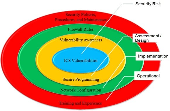 Figure 1. Planning and designing for defense-in-depth
As cyberattacks and the threat of compromised network security continue to rise, so does the need for securing industrial control systems. This includes many different types of systems, with water sector process control systems being one of the higher profile targets because their critical infrastructure affects large populations.
Past statistics from the Cyber Emergency Response Team show recorded cataloged vulnerabilities and reported incidents continuing to rise through the years. A set of “honeypot” ICS set up by Trend Micro to look like vulnerable power and water plants was attacked by hackers 25 times within 28 days. Security is important for the water sector because attacks can damage critical infrastructure that affects public safety; lead to significant operational downtime; cause financial loss, such as the loss of revenue for the utility and its customers; and attract significant media attention causing loss of confidence and fear from the public. There are many resources available that provide guidance on where to start and how to secure networks.
In general, there are four key steps in the process of planning and designing to secure networks for defense-in-depth, as shown in Figure 1. Organizations should use a layered network architecture separating components within a water sector PCS by levels, using access control lists for communications between levels and keeping the most critical parts of the network in the deepest and most secured level of the network. To effectively organize this architecture, it is further necessary to logically segment the system by following industry-standard subnet organization.
Further divide network-connected equipment into VLANs to allow robust communication between critical components that need to communicate and segregating components that do not require communications with each other but communicate over the same media. Subnet organization refers to organizing similar components within a network by IP addresses and more precisely by IP address blocks, or subnets, as discussed in subsequent sections. By designing a layered network architecture that uses logical network segmentation and organization, the network implementation and maintenance can be simplified, further enhancing overall network security.
Differences between corporate IT and water sector PCS
| Water sector PCS | Corporate IT network |
| Real time | Not real time |
| Mainly used for equipment and processes to function | Mainly used by personnel to create and store data |
| Response time is critical | Consistent response time desired |
| Generally low bandwidth | High bandwidth requirements |
| Rebooting must be scheduled or avoided | Frequent rebooting is acceptable |
| Human safety and process uptime are paramount | Data confidentiality and integrity is highest importance |
| System uptime is most critical | System and data protection is most critical |
Table 1. Comparison of water sector PCS vs. IT network operational requirements In modern water sector PCSs, the use of commercial-off-the-shelf (COTS) network components has increased as these systems continue to adopt more Ethernet-connected control system components and budgets for upgrades continue to decrease. COTS solutions provide benefits to utilities, such as ease in getting replacement components, reduced cost, and simpler system integration, but have also been part of the rise in water sector PCS security concerns.
While the COTS components may be the same between corporate and industrial networks, there are critical differences between the requirements of water sector PCS networks and corporate IT networks, as illustrated in table 1. These differences are centered on the fact that water sector PCSs are critical systems that must be kept online and running, while a corporate IT environment can tolerate downtime much more easily and are focused more on the availability and security of data. The differences in these two environments lead to different methodologies in the configuration and use of the similar network components within these systems and in the design of these networks.
For example, corporate IT is fairly flat to allow many users within a facility access to the same data. Additionally, VLANs on an IT network are generally used to segment services and not necessarily to separate portions of the network where data is still required to communicate between devices. A typical corporate network may consist of the following VLANs:
| Typical corporate network VLANs |
| Voice |
| Data |
| Server |
| Management |
| Wireless |
| Public Internet |
Table 2. Typical corporate network VLANs This structure allows a large number of users on the corporate network to have access to the same resources and provides a system where data is highly accessible. For a water sector PCS, it is not desirable for many users to have full access to all data on the network. Conversely, for an ICS and specifically a water sector PCS, data is needed between control processes and by a few operators.
Allowing many users access to this data could be detrimental to process operations and the overall operation of water and wastewater treatment plants. For these systems then, a different network structure is needed. Here, a hierarchical layered network architecture is recommended, where VLANs are used not only to segment specific types of network traffic but also user and equipment groups to limit the accessibility of the data to specific users and processes.
ISA offers standards-based industrial cybersecurity training, certificate programs, conformity assessment programs, and technical resources. Please visit the following ISA links for more information:
- ISA Global Cybersecurity Alliance
- Cybersecurity Resources Portal
- Cybersecurity Training
- IEC 62443 Conformance Certification
- Family of Standards
- ISA/IEC 62443 Cybersecurity Certificate Programs
- Suite of Security Standards
A layered approach to network architecture for increased security
The starting point for a hierarchical layered network architecture is to divide the network into functional zones and to provide a hierarchy from most trusted to least trusted networks to control information flow between zones and access across zones. This description is similar to the nomenclature of zone and conduits set forth in the ISA-62443 (ISA-99) series of standards and the cell and area zones described in the Cisco and Rockwell Automation CPwE design and implementation guide. Typical zones might include the process control zone (most trusted), the PCS data zone, the PCS demilitarized zone (DMZ), the enterprise zone, the enterprise DMZ, and the external zone (untrusted).
The zones are usually arranged bottom-to-top with the most trusted process control zone at the bottom and directly connected to the process, and the most accessible untrusted external zone at the top. Information flow between zones is restricted at the boundaries between zones, and access to each zone, except the external zone, is limited. A general method for devising a layered network architecture can be seen in figure 2. This figure shows a simplified version of the organization of a water sector PCS and a recommended method for separating equipment into zones based on trust level. In general, the Internet and utility or municipality business networks should be seen as untrusted networks and ideally would be air gapped (i.e., not connected). However, there are many advantages to leveraging these untrusted networks to support remote access, reduce communications cost, and provide remote system vendors with access for maintenance and troubleshooting the package control systems.
Other valuable uses of Internet connectivity include remote alarm notification and software and firmware update management. When these services are needed or desired, the remote networks used should be given the lowest trust level (0) possible and direct access should not be allowed to the SCADA or PCS programmable logic controller (PLC) networks. Only the DMZ should have access to the business networks and Internet in order for the layered architecture to be effective.
 Figure 2. Layered network architecture approach
The PCS network DMZ is the location that relays communications between networks external to the PCS network and systems internal to the PCS network. Computers and applications located in the DMZ should be limited to only those necessary for remote access and notification, such as web servers or terminal servers for SCADA human-machine interface (HMI) monitoring, remote alarm notification servers, and software and firmware update servers. In some instances, it may also be necessary to locate a PLC or separate SCADA server in the DMZ to manage data communications with remote facilities communicating through the business network or Internet, and these devices should be separate from those located at higher trust levels within the PCS network. Other systems are likely to also be present in the DMZ, or preferably in separate DMZs, such as physical security related systems, reporting systems, and voice over IP (VoIP) equipment.
These systems should be fully separated from process control systems, and using separate hardware is recommended where feasible. A PCS domain controller is necessary at this level to authenticate and authorize users and apply group policies to further limit access to equipment and applications. It is recommended that the domain controller at this level be a read-only domain controller reading from the domain controller in the SCADA network layer. Within this layered architecture, the DMZ is the first layer of protection for the PCS network and the most vulnerable area of the PCS network. Equipment located in this layer and the functions and applications available in this layer should be carefully selected to ensure critical system components are not compromised. The next higher trusted level in the layered architecture is the SCADA network.
This is the main operator access level into the overall water sector PCS. Within this layer are components, such as SCADA servers, operator workstations, terminal servers (supporting local SCADA users only), and printers to support the main HMI structure of the PCS. It may also include other subsystem devices, segregated on separate VLANs and filtered by the firewall, such as physical security servers and VoIP equipment. The SCADA servers are the central devices in this layer, requiring communications to operator interfaces and communications to the PLC network and DMZ to support process control and remote system monitoring and alarming. A domain controller is required at this layer to support authentication and authorization of SCADA system users. This domain controller is the primary device controlling where user accounts and groups are added and maintained for the SCADA system.
It should not support other systems, such as the security system. This layer does not have direct communications with outside business networks or the Internet, as it is buffered by the DMZ. The SCADA network level is a critical network for operator access and process control but is also often required to communicate to devices in less trusted layers in order to implement remote functions. Communications between layers should be limited to the SCADA servers and domain controllers to minimize available routes across layers. Domain controller communications should be limited to an IPSec tunnel to the read-only domain controller in the DMZ.
The most trusted level in the layered approach is the PCS PLC network, sometimes referred to as the plant floor. This level is the most critical layer in the network and contains the components required for process control and system safety. Ethernet protocols are increasingly being used at this layer, but this layer may include other digital communications protocols, such as Modbus RTU, DeviceNet, ControlNet, Profibus, and Foundation Fieldbus, which can be treated as separate sublayers within the overall system. Within this layer are PLCs to control processes and often additional Ethernet-connected devices used within the process control system, such as variable frequency drives, motor control centers, local operator interface units, digital power meters, and instruments.
A separate physical layer should be provided to support other end devices located in the field for the security and VoIP systems, if necessary, and these systems need to remain segregated from process systems using separate VLANs and firewall rules. Communications between PLCs and process control components within this layer are critical for proper operation and safety of water and wastewater treatment plants.
These systems must be online and operational. By locating critical components within the most trusted layer, they are more difficult to access since multiple other layers need to be compromised first. Process control communications should be given the highest quality of service priority within this level. Using a layered approach to network architecture provides multiple levels of protection for critical process components, and the organization and security of this architecture can be further refined through additional network segmentation for a complete defense-in-depth strategy.
Logical segmentation enhances system performance
A multilevel network architecture has multiple layers of protection for critical process systems and is a critical component of the defense-in-depth protection strategy. Network organization and segmentation provide additional network security, improve network performance and reliability, and help maintain the network. Networks can be organized using appropriate subnets and VLANs, where all devices on each subnet are members of the same VLAN.
Both VLANs and subnets define a broadcast domain, which significantly reduces network traffic by reducing the number of devices that receive each address resolution protocol broadcast. VLANs allow segmentation at Layer 2 where subnets are a Layer 3 construct, so pairing VLANs with subnets allows subnet segmentation to be extended across a Layer 2 LAN environment. This improves network security and further reduces broadcast domains. In this way, overall network costs can be reduced by allowing different VLANs, i.e., separate networks, to reside on the same Layer 2 devices and share communication media (Layer 1). To begin organizing the network addressing, a logical IP addressing strategy tailored to the applications is required to ease network management and support, as well as to allow easy network expansion, upgrade, and adaptation to changing needs.
The Internet Assigned Numbers Authority (IANA) has developed guidelines for private, public, and reserved IP address ranges through a series of request for comments (RFCs), which are managed by the Internet Engineering Task Force. For organizing a PCS network, the private IP address ranges, listed in table 3, are of the most interest and are published in RFC 1918. These addresses are based on IPv4, which uses 32-bit IP addresses. The bit block refers to the number of bits, or IP addresses, available for use within the network, and the class slash ( / ) notation refers to the number of static bits used to define the subnet.
| RFC 1918 Name | Address range | Network class |
| 24-bit block | 10.0.0.0 - 10.255.255.255 | Class A (10/8 prefix) |
| 20-bit block | 172.16.0.0 - 172.31.255.255 | Class B (172.16/12 prefix) |
| 16-bit block | 192.168.0.0 - 192.168.255.255 | Class C (192.168/16 prefix) |
Table 3. Address allocation for private Internets These addresses can then be used without any coordination with the IANA or an Internet registry. Organization within the water sector PCS network should be selected based on the size and topology of the PCS network as well as existing enterprise-wide policies and procedures. A small PCS may not require large-class networks. The following is an example recommendation for a large utility or municipal network:
- 24-bit block: Devices and equipment within a treatment plant or facility
- 20-bit block: Used for connections on private networks between facilities, such as metro-Ethernet, or wireless links such as microwave or frequency-hopping spread spectrum radios.
- 16-bit block: Wide-area-network- (WAN) or metropolitan-area-network-connected devices, such as connections on city- or county-wide networks where the network may be shared with other users
- For large networks, particularly when the business network and the PCS network share resources or network infrastructure, the PCS IP addresses should be carefully coordinated with network administrators to ensure addresses are not duplicated within a private network. By following a standard methodology for IP addressing within a private network, it becomes simpler to prevent address duplication and to manage the different PCS networks. The steps involved in developing the IP addressing scheme include:
- Making a list of primary network segments
- Laying out a rough network topology with Layer 3 interfaces separating primary network segments
- Developing an initial IP numbering strategy
- Creating a strategy and continuing to add detail and make adjustments as required
- Ensuring that the scheme has the capacity and flexibility to accommodate expansion and to adapt to the ever-changing network environment
For each subnet assigned on the network, a VLAN number and description needs to be assigned. The default or native VLAN is VLAN 1. IP addresses not assigned to any other VLAN will be assigned to this VLAN, making it subject to intrusion. For this reason, it is generally recommended to avoid use of VLAN 1 to enhance network management and security. The following is a recommended approach for the use of VLANs within a PCS network:
- Use VLANs in the range of 2-1001; various restrictions apply to other VLANs
- Do not use VLAN 1 (default or native VLAN)
- Use devices that support IEEE 802.1q VLAN Encapsulation Protocol
- Use a logical approach in VLAN number selection to support network management
- Incorporate VLAN numbers into IP addresses
By using the recommended approach, VLANs can provide network segmentation and aid in network management and organization. Combining a well-thought-out VLAN approach into an IP addressing plan can improve network management, device IP address assignments and identification, and security. An example approach to combining VLANs into an IP addressing scheme is shown in figure 3.
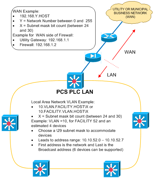 Figure 3. IP addressing example
The major components of the IP addressing example in figure 3 are the facility and VLAN numbers. Facility numbers can generally be selected by actual facility numbers or unit process numbers associated with a facility to make the IP address a usable and recognizable number. VLAN numbers can be anything in the allowable VLAN range; however, the following approach outlines a method of selecting VLAN numbers to aid in equipment identification and to aid in trust level identification and firewall configuration:
- Organize VLAN numbers in a similar order as trust levels (e.g., VLAN 10 is most trusted, and VLAN 900 is least trusted).
- Separate VLAN numbers selected to allow for future growth and make addresses more distinguishable. Use VLAN numbers such as 10, 20, and 40.
Figure 4 shows an example VLAN selection scheme based on the recommended approach for selecting VLAN numbers and a network topology similar to that shown in figure 2. In this example, VLANs start with 10, with the highest trust level being the network management VLAN.
This VLAN would be solely used by the network administrator to use network monitoring and management software and would have access to all equipment on the network. The VLAN order then closely follows the layered architecture shown in figure 2, where the PLC network was the most trusted network and the utility WAN was the least trusted layer in the example architecture. Additional VLANs can be assigned as required for other systems and networks to meet the requirements of the PCS. By completing a detailed network assessment and devising a network security strategy, a successful network segmentation scheme can be planned and designed to allow for logical segmentation of water sector PCS networks.
This logical segmentation can aid in network organization and identification of networks, locations, and components with a PCS network and can be used in conjunction with a layered network architecture and security rules for an organized approach to overall system cybersecurity.
 Figure 4: VLAN selection example
Coordinating network architecture and segmentation for a complete solution
Adding VLANs as part of the network segmentation plan for a multilayered PCS network architecture provides additional security, lowers network utilization, and makes network management simpler. Combining these solutions helps to eliminate unnecessary routes through the layers and reduces network traffic, which improves both network security and optimization. Figure 5 shows an example water sector PCS control center LAN architecture utilizing the network segmentation approach previously presented.
 Figure 5. Multilayered PCS network architecture with segmentation
Figure 5 is an example of a typical PCS network with remote access and communications to other remote PCS control rooms that are physically separated to allow coordination across the water sector utility. Figure 5 is an example for a PCS network for remote pump stations. In this case, the pump stations have PLCs located remotely throughout a municipality that must be polled and data reported to a central SCADA system for monitoring and control. In this example, the local network is broken into multiple VLANs as shown in figure 6.
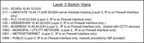 Figure 6. VLAN assignments
As shown, multiple VLANs reside at Layer 2 and can communicate with other components on the same VLAN using only Layer 2 devices, thereby allowing separation of different network components but allowing communications using less expensive Layer 2 devices for the PCS LAN. In this example, the SCADA network is the most trusted network, because it is located in the innermost layer of the network. The PCS PLCs are the next most trusted component in the network since they poll data from remote pump stations via point-to-point VPNs with data encryption. This is reversed from the network architecture in the example of figure 2, showing that network assessment and planning are necessary to identify the critical components of a network and that water sector PCS networks are unique. They require customized solutions that follow a standardized practice.
Continuing with this example, VLANs 10, 11, 20, 30, and 40 reside on the local network and are trunked at the local firewall for the network. This firewall provides both routing and access control lists that govern communication between the VLANs on the network. Additional communications routes are also provided to a remote control room. These communications consist of a primary route through the utility/municipality network, as well as disaster recovery communications through a private metro-Ethernet network.
The configuration of the VLANs for each of these networks simplifies the allowed communications between these networks. As noted previously, communications between PLCs are done through remote VPN connections, but PLCs are still all on the same VLAN to allow direct communication between PLCs without the need for a specific route to be established. Figure 7 shows the remote VPN connections needed for remote device communications. Note that only VPN connections are necessary and that additional routes do not need to be established since devices that need to communicate with each other are on the same VLAN.
 Figure 7. Remote connections using VPNs
By combining a layered architecture with logical network segmentation, network organization and remote communications are simplified. The effort needed to establish communication routes and access control lists is simplified making network configuration and management easier. Figure 8 summarizes the VLAN and subnet organization for the example architecture. (click on image to see a larger version)
 Figure 8. Example IP addressing scheme (click on image to see a larger version)
Configuration and management
One of the main features of a logical segmentation plan within a multilayered network architecture is a simplified approach to firewall configuration, thereby making network security and routing management simpler. Using VLANs to coordinate similar equipment with similar access rights and trust levels makes routing and access control list configuration for communications between subnets on the network easier. Communications routes between networks for devices added to a given VLAN are then already in place.
Network expansion is then simplified because new routes and rules within network security and routing appliances do not need to be added or revised each time a piece of equipment is added to the network. Figure 9 shows an example firewall trust level configuration for the network presented in figure 5. This example exhibits how trust levels can be defined simply for large groups of network-connected equipment based on VLAN assignments.
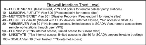 Figure 9. Firewall trust levels
Figure 9 depicts the trust levels for the various VLANs and notes global rules for each VLAN, such as what other networks or VLANs each trust level is allowed to access. To provide a complete security configuration, additional access control rules are necessary to further define allowed communications between networks. Using VLANs with associated trust levels simplifies global rules, which make implementation and management of the network simpler.
Figure 10 is an example of firewall rules and allowed VPN tunnels for the example shown in figure 5 and trust levels summarized in figure 9. Figure 10 is a summarized form of the rules to be implemented in an actual firewall. It shows how organizing a network into subnetworks using VLANs can greatly simplify the rules implemented in an actual firewall.
 Figure 10. Firewall access control rules
As shown in figure 10, each set of rules is defined by VLAN, or could be defined by subnet, but not by each device or each specific IP address. Having an organized network approach then allows for global definitions of access control lists and global management of devices within groups in lieu of having to manage each device separately. By combining similar devices into groups by planning and organizing the network, network configuration and management is simplified.
Conclusion
The approach for a multilayered water sector PCS using VLAN segmentation for subnetworks provides a foundation for which secure PCSs can be developed. By using the strategies and tools such as the four-phase process of assessment, design, implementation, and procedures/maintenance, a water sector PCS network can be customized to provide a secure and manageable PCS network.
As with any system, planning and design must be carefully coordinated to ensure components are located within the correct layer of the architecture and that the proper firewall rules and access control lists are implemented. By using VLANs, this segmentation can be extended across a Layer 2 LAN. The advantage of the approach presented is that it allows for simpler configuration of network security appliances and for simpler management and expansion of the network, leading to increased network availability and a reduction in threat risk as part of a comprehensive defense-in-depth strategy.
List of acronyms |
|
| ACL | Access control list |
| CERT | Cyber Emergency Response Team |
| COTS | Commercial-off-the-shelf |
| DMZ. | Demilitarized zone |
| HMI | Human-machine interface |
| ICS | Industrial control systems |
| IP | Internet Protocol |
| IT | Information technology |
| MCC. | Motor control center |
| NIST | National Institute of Standards and Technology |
| PCS. | Process control system |
| PLC | Programmable logic controller |
| SCADA | Supervisory control and data acquisition |
| VFD | Variable frequency drive |
| VLAN | Virtual local area network |
| VPN | Virtual private network |
| VoIP | Voice over IP |
About the Author
Norman Anderson, P.E., has more than six years of experience in the design and commissioning of process control systems and security systems for the water sector. Norman has provided secure and reliable PLC, SCADA and network hardware and software architecture designs and provided control system automation solutions for a range of facilities. He has an M.S. in electrical engineering from Iowa State University and an M.S. in physics from the University of Florida.
Connect with Norman![]()
About the Author
Bill Phillips, P.E., specializes in the delivery of secure and reliable process control and SCADA network and communications systems, cybersecurity vulnerability assessment and facility automation and information system planning and implementation. Bill has more than 30 years of process control and SCADA system experience and has focused on control system network and communications cybersecurity for the last decade. He has a B.S. in electrical engineering from Clemson University.
Connect with Bill![]()
A version of this article also was published at InTech magazine.

